Parallel imaging is the one of the advanced techniques recently developed in MRI. It is based on the spatial information inherent in phased array Radio frequency coils and reduces the scan time. In PAT the number of sampled K –space line is reduced, often by a factor of two or greater there by significantly shortening the acquisition time .It can be used in FSE (or TSE) and SS FSE (or HASTE) to improve spatial resolution by reducing ETL. It is used in 90 % of the sequences in higher Tesla machines. The limitations of PAT include reduced SNR and reconstruction artifacts.
History of PAT
The introduction of multiple overlapping small coils replace the large coils,as it cover the same volume as the large coil. when the signals from individual coils are combined, the noise is substantially reduced and SNR is significantly improved. the introduction of multiple overlapping small coils leads to the introduction of phased-array Coils.
The phased array coils operate typically as receive only coils. In that case, in the MRI device implemented body coil act as thetransmitter and sends the radio frequency energy to generate the excitation pulses. State-of-the-art array coil systems include the use of 4 (up to 32) coils with separate receivers. This method is often referred to as a phased array system, although the signals are not added such that the signal phase information is included. The use of phased array coils allows the decreasing of the number of signal averages, which shortens the scan time by high SNR and resolution.
Theory –(basic)
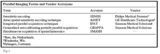
The basis of these techniques is the concept that acquisition time is proportional to the number of phase-encoding lines in a Cartesian acquisition. Increasing the distance between phase-encoding lines in k-space by a factor R while keeping the spatial resolution fixed reduces the acquisition time by the same factor. This also decreases the field of view (FOV), resulting in aliasing or wraparound artifact .In parallel imaging, the spatial dependence of the phased-array coil elements is used to remove or prevent the aliasing in Fourier transform. Different vendors uses verity of techniques based on PAT .
The different vendors and their techniques are shown in a table
fig-2
Figure 2. Example of the SENSE technique. Reference image of a phantom (a), obtained with the
body receiver coil. Sum-of-squares image (b) from two individual coil elements. Spins at spatial locations closer to the coil elements (arrowheads) exhibit higher signal levels than those that are farther away (arrow). A corresponding reference k-space containing 20 phase-encoding views is shown at left. FT = Fourier transform. Low-resolution full-FOV calibration images (c and d) for each coil, which were obtained to calculate the complex sensitivity profiles of each coil element. Sensitivities (s1 and s2) of each coil element are illustrated at two arbitrary points. Reduced-FOV SENSE images (e and f) from each coil element contain extensive wraparound artifacts along the superior-to-inferior phase-encoding axis. a1 and a2 represent the signal intensities of the aliased images that correspond to the arbitrary points chosen in c and d. Diagram of the unaliased image (g) with desired pixel intensities p1 and p2. These intensities can be calculated because the sensitivities of the individual coil elements and the pixel intensities of the aliased images are known. Unaliased image without (h) and with (i) intensity correction, which represents the SENSE-reconstructed image.
Applications of PAT
- MR Angiography- fig-3
- Dynamic Contrast-enhanced Imaging - fig-4
- Fast SE Imaging - fig-5
- Cardiac Imaging - fig-6
- Breast Imaging - fig 7
- MR Enterography and Colonography - fig 8
Limitations of PAT
Limitations of parallel imaging include reduced SNR and reconstruction artifacts. It is important to consider these limitations when deciding when to employ these techniques.

Figure 3-Partial volume maximum intensity projection images from renal MR angiography of a patient with fibromuscular dysplasia, obtained without (a) and with (b) SENSE (acceleration factor = 2, applied in the inplane right-left phase-encoding direction). In the standard image, early filling of the left renal vein limits visualization of the left renal artery. Venous contamination is eliminated in the SENSE image, which was obtained with the acquisition time reduced by half. Collecting system activity in the SENSE image is due to excretion of contrast material from the first non-SENSE acquisition

Figure 4 Axial arterial phase (a, b) and portal venous phase (c, d) fat-saturated 3D SPGR images of a patient
with a metastatic neuroendocrine tumor. The images were obtained with SENSE (acceleration factor _ 2, applied in
the anteroposterior phase-encoding direction), with a and c acquired slightly superior to b and d. SENSE was used
to achieve both excellent temporal and excellent spatial resolution. In this case, achieving optimal timing and adequate
coverage in the arterial phase was crucial because many of the early enhancing hepatic and osseous metastases
could not be visualized on images from subsequent phases.

Figures 5) Coronal single-shot fast SE image obtained without (a) and with (b) SENSE (acceleration
factor _ 2). Although the SENSE image has slightly diminished SNR, it also has slightly less blurring. (13) Maximum
intensity projection image from 3D fast-recovery fast SE MR cholangiopancreatography. SENSE (acceleration
factor _ 2) was used to reduce the acquisition time sufficiently so that an adequate volume could be obtained within
a comfortable breath hold.

Figure 6. Short-axis cardiac steady-state free precession cine images (in end diastole) obtained
from apex to base by using SENSE (acceleration factor = 2). Three sections were acquired per
breath hold, allowing the total acquisition time to be considerably shortened.

Figure 7. Sagittal image of a patient with residual breast carcinoma after an excisional biopsy, obtained with a dynamic contrast-enhanced 3D fat-saturated SPGR sequence. Use of
SENSE (acceleration factor = 2) allowed coverage of both breasts with adequate spatial resolution and adequate temporal resolution.

Figure 8. Coronal contrast-enhanced fatsaturated 2D SPGR image of a patient with
Crohn disease shows mild thickening and enhancement of the terminal ileum. SENSE (acceleration factor 2) was used to reduce the acquisition time and thereby decrease motion artifact caused by peristalsis
Note-PAT-Parallel Acquisition Technique, FSE-Fast Spine Echo, TSE-Turbo Spine Echo,
SS FSE-Single Shot Fast Spine Echo, HASTE-Half Acquisition study Time Echo, SNR-signal to Noise Ratio, ETL-Echo Train Length, FT = Fourier transform, SPGR-Spoiled Gradient Recalled Acquisition, Crohn disease –it is an inflammatory disease of the intestines


